Part 2
Click here for Part 1So now the work really begins with phase 2. Two new tires are on the way, and when they get here next week I hope to have the old tires off, the brakes inspected, the bearings repacked, and the chain clean and re-lubed. Who knows, if everything goes right, I might even have time to do a few engine related things. My ebay purchased owner's manual arrived today, and I was fascinated by reading it cover to cover. It has several very handy bits of information, including a list of the contents of an original tool kit. This will be especially handy as I try to assemble a functional replacement for my own adventures. I've also had time to read up a bit more about engine tune-up items, and I think I'm going to start with an oil change and filter cleaning. I can't wait to see if there is any volume of debris in the oil filter, especially since I didn't do anything with it the first time around. I think I'll feel a lot better about spending time messing with the carbs if I know that at least the timing, valve clearance, and that kind of stuff has been checked by me personally. I'll also feel a lot better about going any faster than 35 miles per hour with tires that are newer than 35 years old. The ones that are on the bike now are original. Yikes!
Armed with manufacturer recommended maintenance schedules, I set out to complete most of what the tune-up items listed. I started with a valve clearance adjustment. I found that there was no valve clearance initially, which made for some confusion in positioning the engine. Both books say to align the timing mark and then determine which cylinder is in compression by wiggling the rocker arms. The ones that are noticably looser are supposed to mark the cylinder that is up to compress. (Keep in mind that both cylinders operate in unison; they are both going up at the same time, with one compressing and one exhausting). Since the valves had no clearance, all of the arms were tight. I compared the position of the arms to find which ones were in a valve-open position, since there is a noticable difference of close to 1/4". After adjusting the clearance, I saw exactly what the authors were talking about.
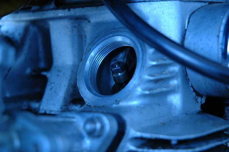
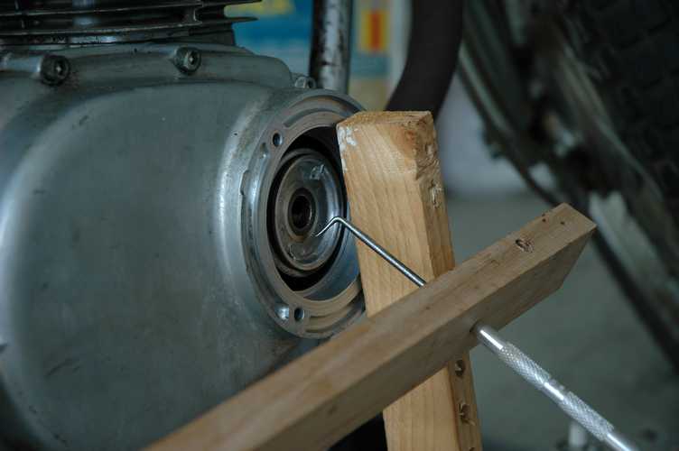
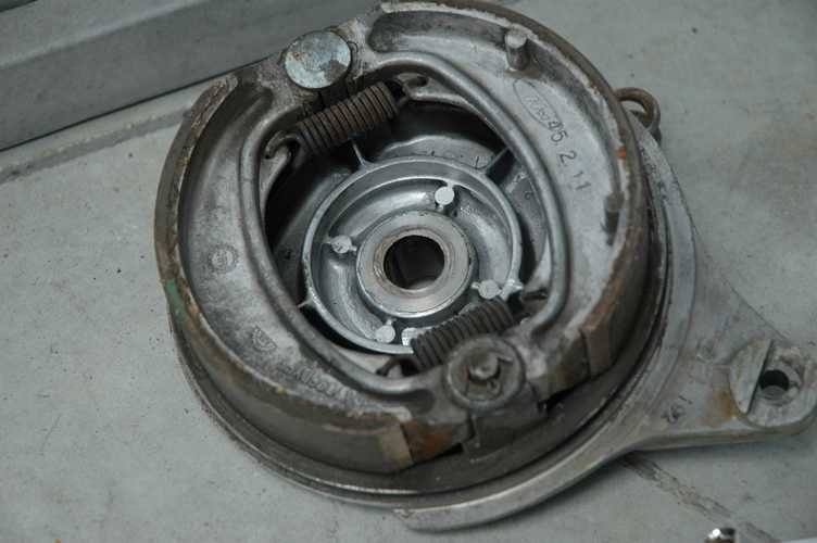
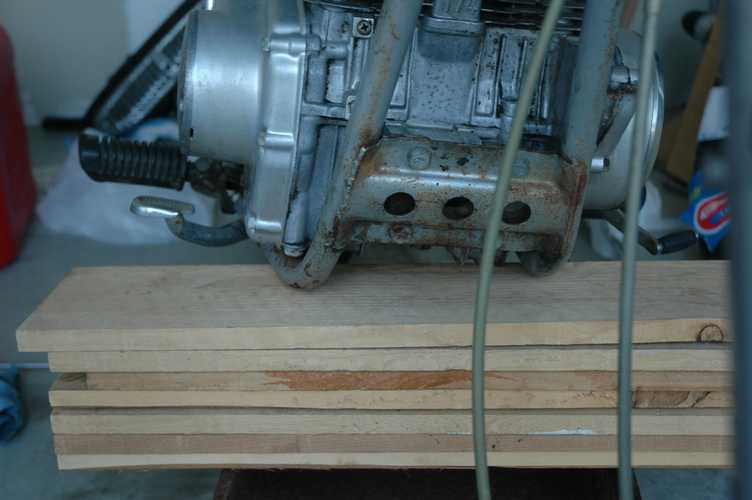
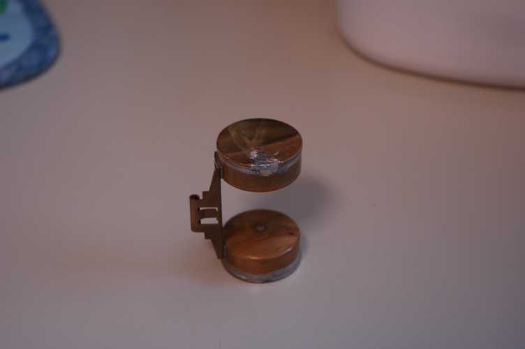
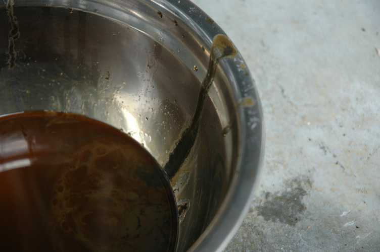
I wanted to at least take a look at the centrifugal oil filter, considering the age and other circumstances. After removing a few stripped screws, the books told me that I should be able to remove the cover for the filter can and look inside. I was especially worried because one of the two tabs on the cap was already broken off and I didn't want to break off my only other option. After some considerable head-scratching and a few failed ideas, I came up with a home-made tool to do the job. The only missing part in the picture is a 1/4" socket extension which served to keep the scribe located inside the filter. The leverage of the wood that the scribe is in (oak) was enough to work the piece off a little at a time. For the record, I found only a little bit of sediment in the filter, most of which was a slightly metalic sludge that scraped out pretty easily with the scribe.
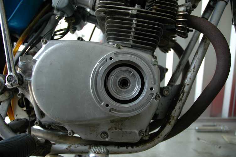
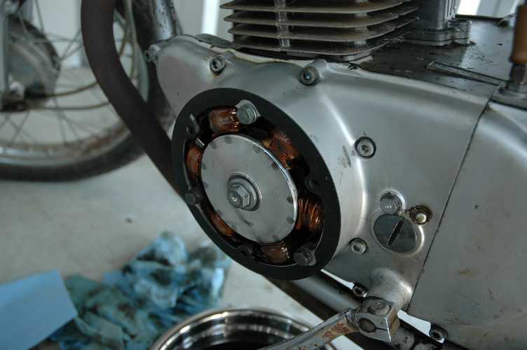
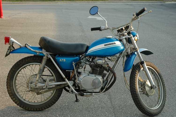
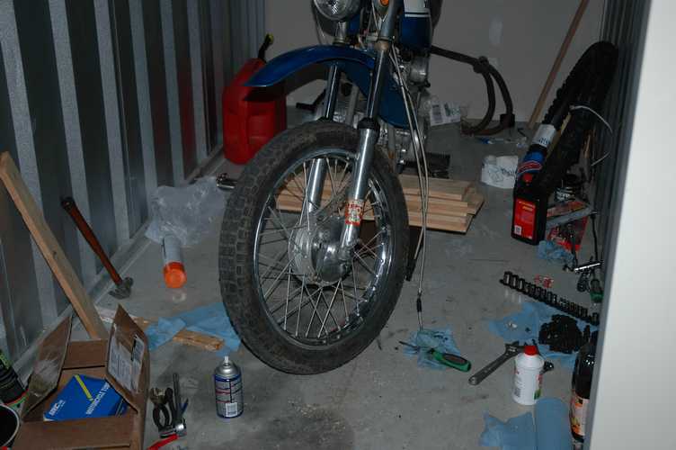
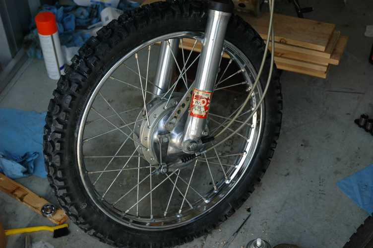
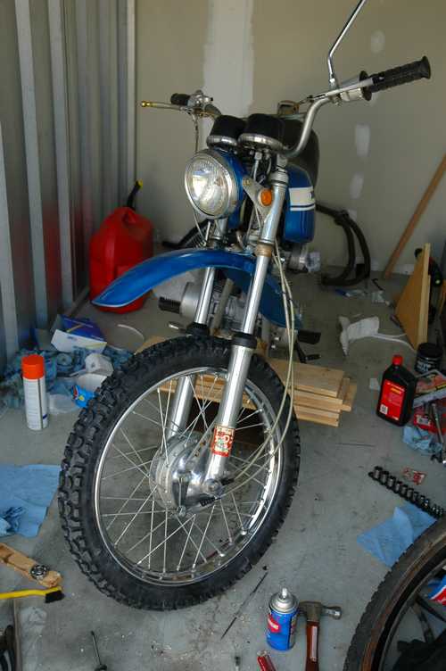
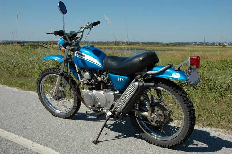
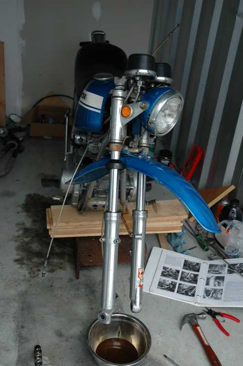
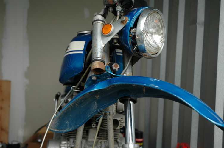
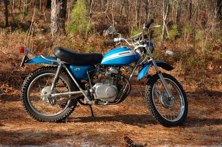
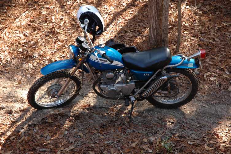
With those tasks done, I took the opportunity for a few pictures before starting on the wheels.
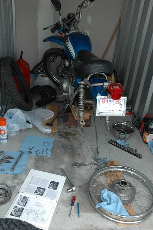
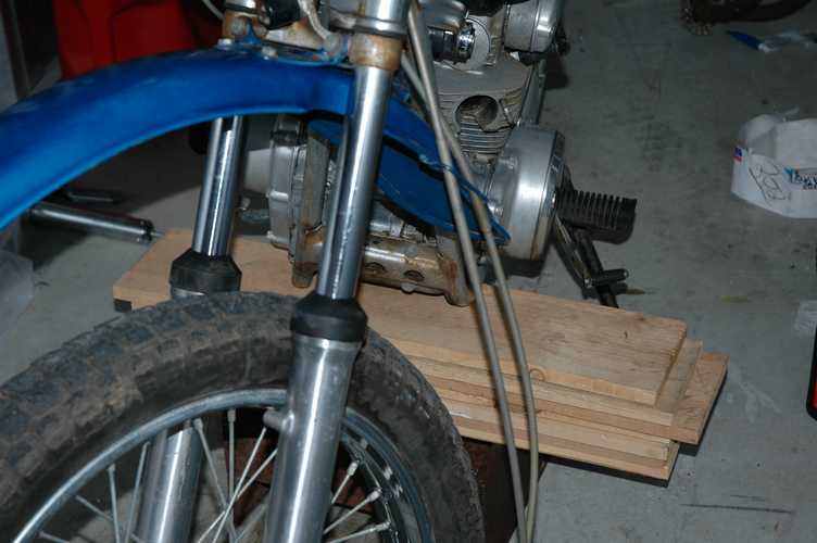
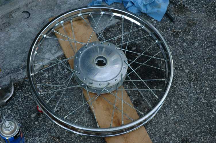
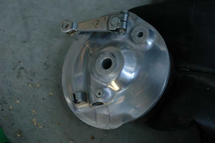
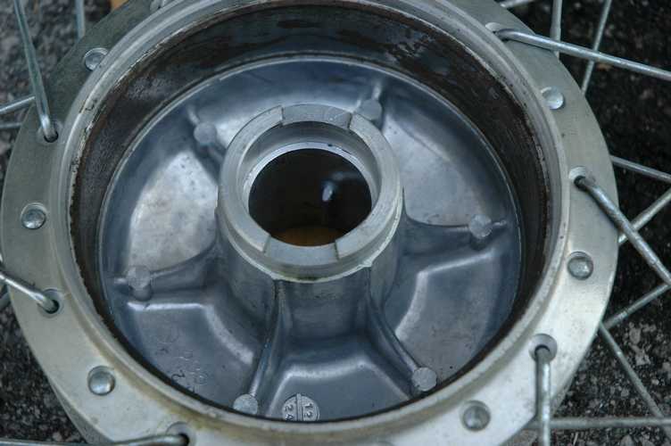
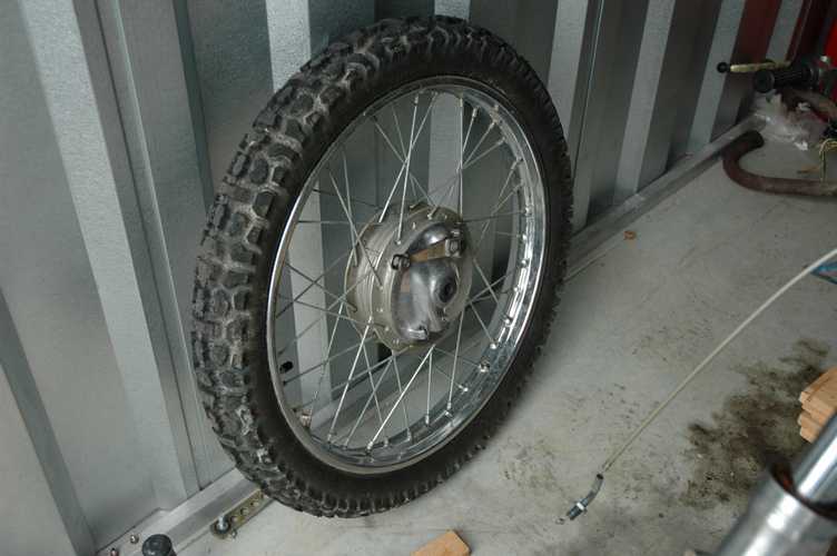
Since it doesn't have a center stand, I rigged up a stack of stuff that would serve the purpose. Since Honda put the exhaust pipes below the frame, I had to remove them so that the frame would support the weight alone. I could only remove one wheel at a time with this configuration, but it was just as well. I started with the rear wheel, following the steps in the shop manual. Everything looked good, though the wheel bearings were better off with some fresh grease. I took the chance to polish the rim while I had the wheel off, and I was surprised at how well they turned out.
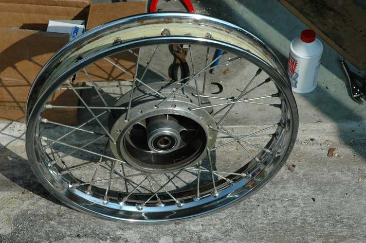
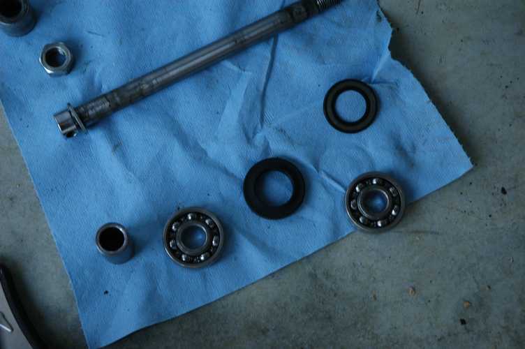
The back wheel went well enough, though I didn't remove the bearings. They are a drive fit, and I didn't want to risk making matters worse by damaging them. On the front wheel I was able to remove them, and I found $10 replacements at the local industrial supply place. By comparison, my local auto parts store wanted $20 to order it, and I didn't bother checking the motorcycle shop.
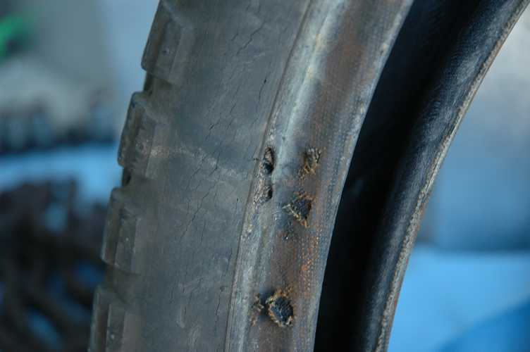
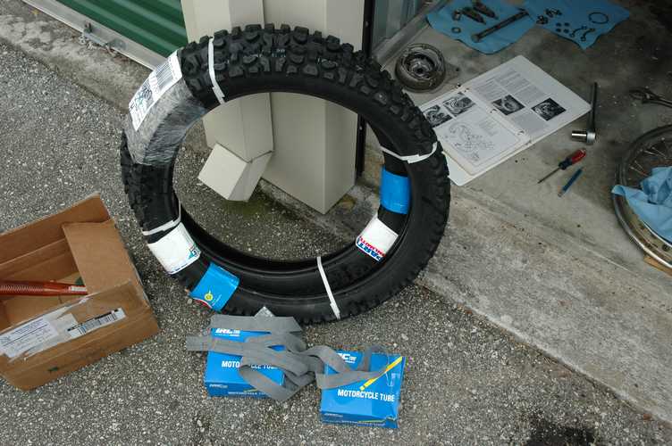
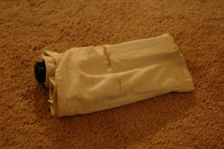
Note the small hole created in the sidewall of the old tire by some kind of burrowing insect. It is just outside of the scuffs that I made while taking the tire off.
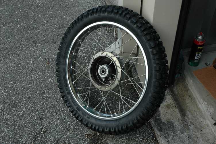
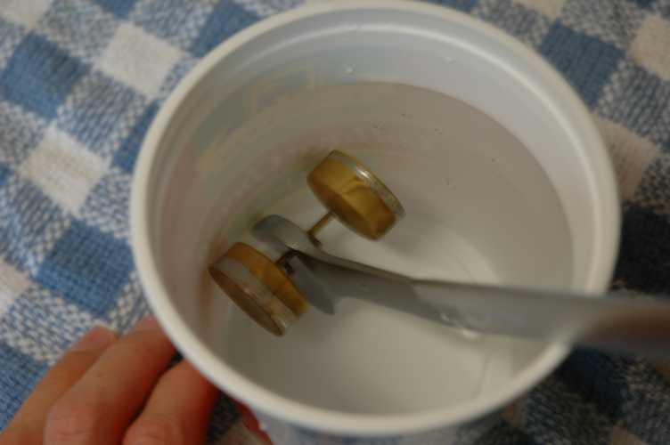
After replacing the tires, I set out on a few riding adventures. I found that the bike likes to cruise along at about 45 miles per hour and 6000 RPM. It will go as fast as 60, but it is obviously working pretty hard at that speed. I found a few trails and even rode around for a few hours in the sandy woods. It did very well off-road, at least by my inexperienced standards. I rode over to the coin-operated car wash only to find a trail of fuel behind me. It turns out that the right carb float had developed a very small hole, and the float had been very slowly filling with fuel. Since the float is made of brass, I located the hole and used a dremel to enlarge it. The only way of finding the hole was to clean the outside of the float, wrap it in a dry paper towel, and shake until a small wet spot showed up on the towel. I sprayed a little bit of carb cleaner to help remove any additional residue, and then soldered the hole. I used an open-end wrench to hold the float submerged overnight and found no additional leaks. In spite of the off road riding and the fuel leak, I averaged 62 miles per gallon.
April 2008 Update: Note! I do not recommend attempting to repair a float this way. I've done it twice now, and both times it worked for a little while and then started leaking again. If you need to repair one to get yourself home, then do it- but be ready to buy a new one once you get there. I also have concerns about changing the weight of the float substantially. Carburetors are extremely picky about everything, and I have found that it just isn't worth introducing another variable.
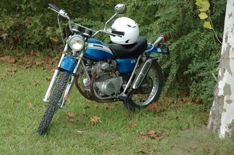
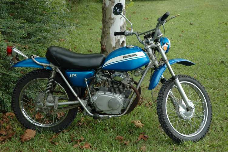
I set out on a few more riding adventures. The first picture is at Wrightsville Beach, and the second are at a small airport in Burgaw NC. After an additional 100 miles I'm reminded about the oil leak on the right side, and some other leaks somewhere else. I've since removed and replaced the gasket on the tachometer drive in hopes to reduce the oil leak. I think another leak is coming from the float bowl gaskets, so I have replacements on the way. Hopefully that will do good things for the floor under the bike if nothing else. I'll know next time that I get to do some riding!
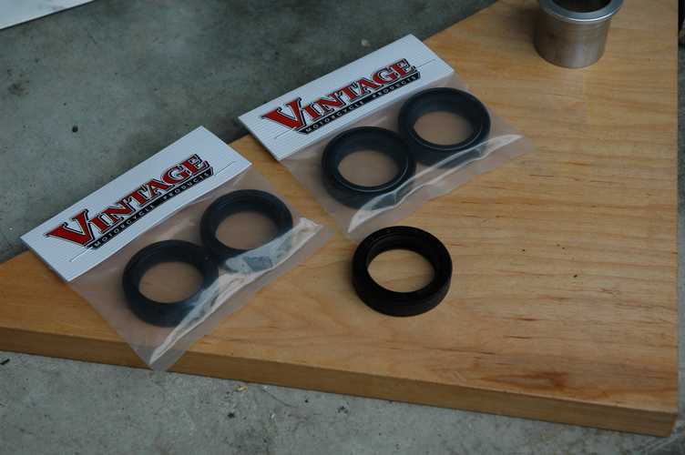
It turns out that the bulk of the oil leak seems to be coming from a location yet to be discovered by me, so for now I have accepted it as part of my continuous oil change program, or rather my automatic external corrosion protection program. In the mean time, I decided to replace the fork oil seals and oil, since they were presumably original.
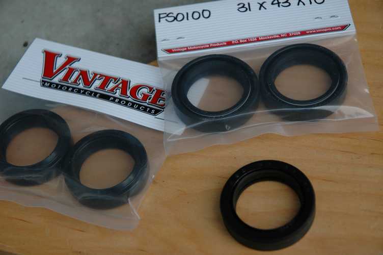
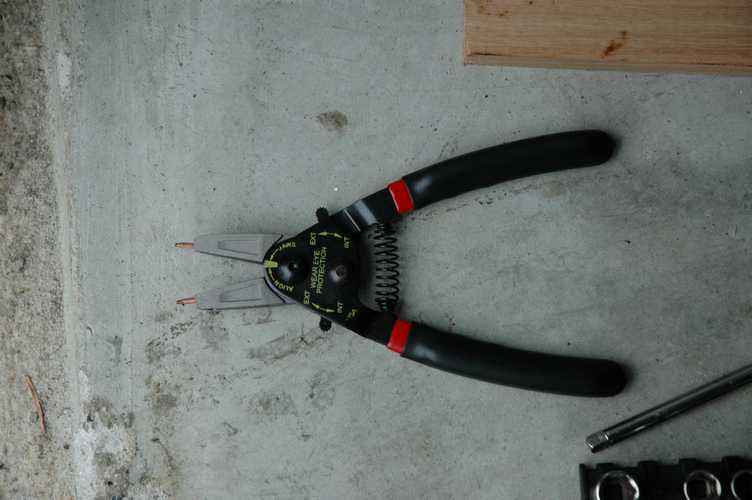
The first step was to order the oil seals. I found them on ebay from a seller that specializes in old motorcycle parts. After a few mix-ups with shipping, I finally ended up with the 31x41x10 seals that I needed. The next step was a trip to sears for a new set of snap-ring pliers. The smaller set that I had just wasn't cutting it for the 2"-ish inside rings on the top of the forks.
April 2008 Update: These fork seals have leaked since shortly after I put them in. I do have another set to try and replace them, but consider that problem before you subscribe to my advice in this section.
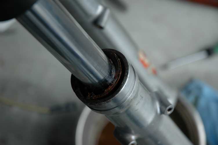
When I took off the ring, the old seal didn't exactly come right out. There are some differences between my SL and the CB/CL that my Haynes book covers, and I know that the fork was one area that Honda did differently between the models. I wasn't sure that there wasn't anything holding the fork together other than 35 years of cling, so I tried to pull the shiny piece and the bottom piece apart. It didn't budge when I pulled with one in each hand, so I tried more drastic measures by sticking a 3/8" socket extension through the axle hole, standing on either side of the protruding extension, and yanking the shiny part in a weed-pulling fashion. That didn't exactly work either. Rather than pounding on pieces that I didn't know were free, I attempted to excavate by destroying the old oil seal, so that I could see what was on the other side. After a day of creative levering with wood screws and picks, I found that there were in fact no other mechanical reasons for the parts not to separate.
This hard-learned lesson sure paid off when it came to taking apart the other side. I put the extension back in on the bottom, and instead of applying a firm yet reasonable weed-pulling motion to the shiny part, I gave it a more persuasive attempt. After 2 or 3 minutes of what must have drawn the attention of anyone who could see me, the antique cling finally gave in to modern pounding. Even though this was much more effort than I would have wanted to apply, it saved a day's work to get the same job done.
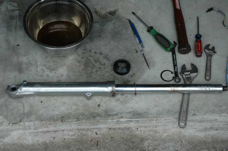
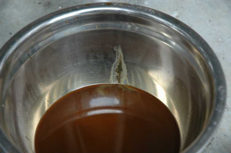
The really gross part was draining the oil from the forks. I unscrewed the plug at the bottom of the first fork very slowly, expecting anything from a seep to a gush of old oil. I was surprised to find that I had the screw in my hand and yet there was no flow. This reminded me of cartoons where a character walks off of a cliff only to continue as though the ground was still there, without falling into the valley below. With a few pokes from a scribe, the oil started to drip. The most effective tool for clearing out the hole was actually the leftover plastic piece from a wire tie. It was just the right width, and I knew there was no risk of damaging the aluminum threads since it was made of plastic. Once the oil started flowing, I saw a colorful rainbow of everything from black to milky yellow and rusty brown. Click on the pictures to see the larger version.
Once I reassembled the forks, reattached the front wheel and cables, removed my homemade jack-stand, reinstalled the exhaust (whose removal was required to accomodate the previous), and cleaned up the mess, I was ready for more riding. The storage place that I use for a garage is also popular for medical record storage. One of the regular workers pointed out that I seem to work on the motorcycle more than I ride it, and I am starting to agree. The good news is that other than the engine gaskets, the cables, and a few other things, I don't have much more to work on. That is, until the parts that I have replaced start to need replacement again.
April 2008 Update: Herein lies my problem. I should have never made such a statement! Little did I know back then, but I actually had several more things to replace and repair, and still do! At least I wasn't standing on an aircraft carrier when I said it.
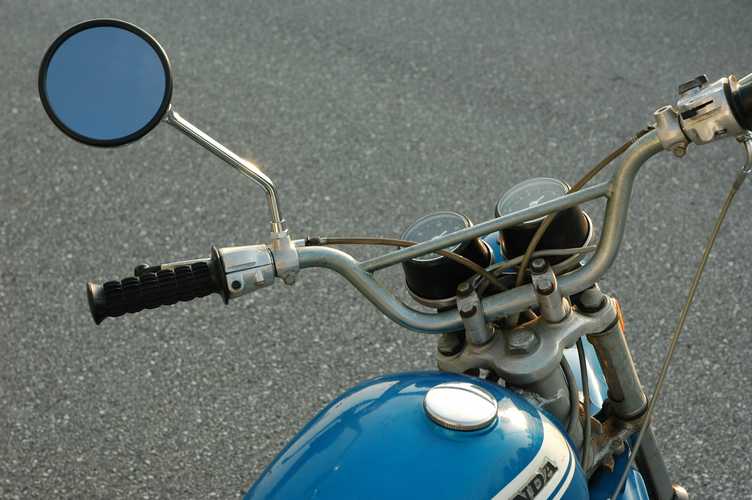
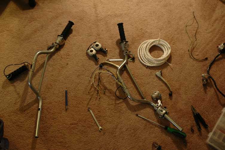 And of course, while I had the front end apart, I decided to replace the handlebars. They seemed to have encountered a bit of a tweak due to some pre-fork seal off-road adventures (see hill below) and I found a cheap replacement on ebay complete with several attachments. Someone was probably parting one out, and just sold everything from the mounts up in one grab. It was tricky to take my wiring harness out (which was in better shape than the replacement) and even more tricky to reinsert it in the new handlebars. The rest was a matter of picking the parts in the best condition for the rest of the controls. I took the opportunity to replace the non-OEM throttle grip that was on mine with the original one that came with the replacement handlebars. My theory was that I would use the parts that I needed and then sell the rest on Ebay, and so far those sales have generated about half of what I paid for the whole batch. Not so bad of a deal if you ask me... after all, salvage is one of my top 5 secondary career choices.
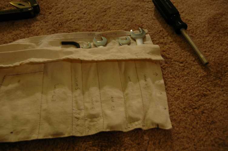
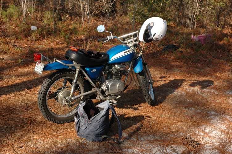
The contrast to working in the comfort of my little mini-garage is repair on the trail. Luckily my owners manual detailed a list of tools that were included with the OEM toolkit. I used this list to reconstruct a similar kit, and my mom was nice enough to sew a canvas holder for them all.
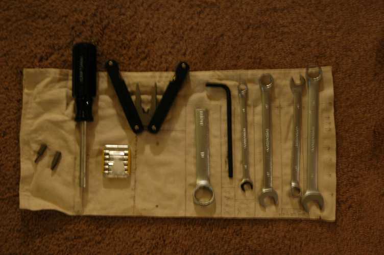
My kit includes:
8, 10, 12, and 14mm wrenches
Half of a 19mm wrench (oil drain, etc)
5mm allen wrench (this is my addition to accomodate aftermarket screws holding the engine case etc)
An interchangeable screwdriver with a few different bits
A multi-purpose leatherman knock-off
A few extra 15A fuses
The canvas pouch to hold each piece
With some careful packing, this whole set fits in the little pocket under the seat pan.
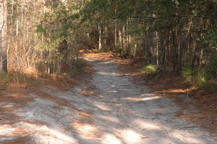
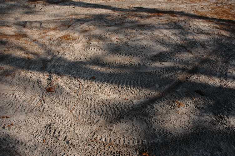
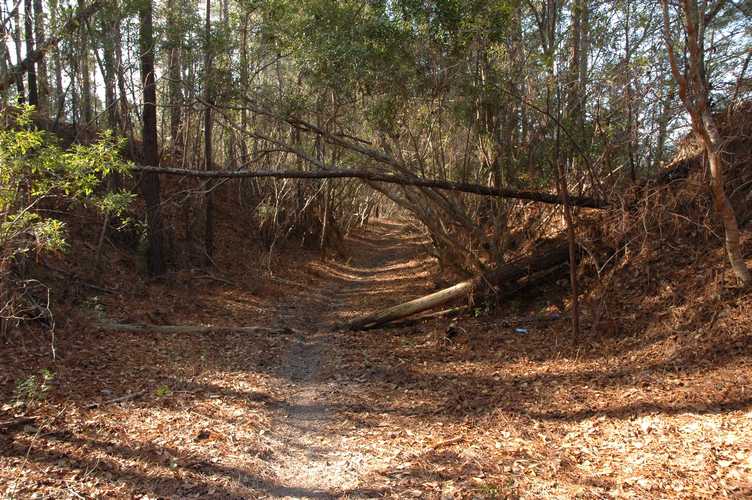
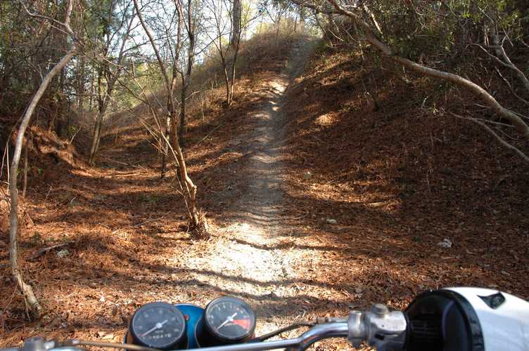
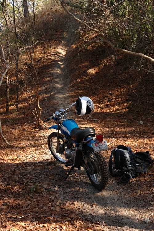
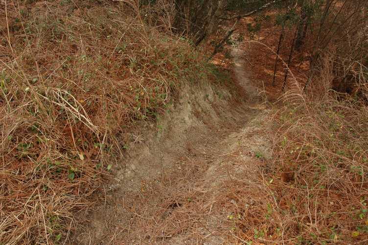
Here are some pictures of trails that I've ridden recently. You can see a giant hill, which was a bit too giant for me to make it up the first time. I was riding with Matt, who was kind enough to send me up the granny version of the trail that features a few short hills instead of one long one. Unfortunately, I didn't understand his communication, and by the time I realized that I was going up the hill, I was in the wrong gear and short about 200cc of engine displacement. The end result was a little bit of a bend on the handlebar, which was easy to fix as noted above.
Check back for updates on repairing spark plug threads, replacing cables, and more as I slowly save up extra cash.
Click here for part 3, the engine.